Last tutorial I has give a simple example how to use open source PIC basic using GCBasic. This tutorial I used 7 segments to display a number using PIC16F84A. Usually 7 segments need about 8 wires to operate using PIC but in this tutorial I only used 3 wires.
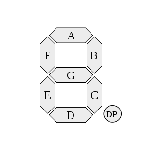
Seven segments display have 7 elements of LED to show Arabic numerals. Each element of LED can be ON or OFF and they can be combining in order to produce representation of the number. They also can be produce letters but it limits letters A to G only. The elements of LED is arrange as below.
Typically 7 segments have two types. The types are common cathode and common anode. The common cathode is referring to negative terminals and anode is positive terminal. It means the negative or positive terminals of the each LED elements are connected together and brought to common pin. Hence a 7 segments plus decimal point package will only require nine pins.
As mention earlier I used only 3 wires to operate the 7 segments. In order to have that IC 4094 shift register was used.
The 4094 is an 8 bit SIPO shift latch register. The device consist of 8 bit shift register and an 8 bit latch with 3 state output. It also have 3 importance input. The inputs are strobe, serial in and clock. The circuit connection between the PIC16F84A, IC 4094 and 7 segments were connected as below.

The Data, clock and strobe are connected to RB0, RB1 and RB2 respectively. The 7 segments are connected to Q0 to Q7 pins of 4094 with A to G pins and DP pin of 7 segments. The type of 7 segments is common cathode. The OE is connected to 5V. It makes sure the IC is always ready to operate.
The data will send by PIC16F84A to 4094 trough pin of RB0. The 8 bit data of the PIC will shift serially to the 4094. The IC then shift the data to shift registers at the positive transition of the clock input. The clock input also trigger by the PIC. When the strobe input is give high by the PIC the data will propagates to the output pins of Q0 to Q7.
The output of the 4094 then will ON or OFF the 7 segments LED depending on the data input. The 7 segments will display a number responding of it. Below is the program of the microcontroller.
'A program to flash two LEDs on PORTB, bits 0 and 1
'Chip model
#chip 16F84a, 4
#define data PORTB.0 'set as data #1
#define clock PORTB.1 'set as clock
#define strobe PORTB.2 'set as strobe
'Set the pin directions #2
dir PORTB out
'Main routine
Start:
set data off 'put data low #3
for loopcounter = 1 to 8
PulseOut clock, 10 ms
PulseOut strobe, 10 ms
next
segment = b'11111100 ' #4
for loopcounter = 1 to 7
nsegment = segment % 2
data = nsegment
PulseOut clock, 10 ms
PulseOut strobe, 100 ms
segment = segment / 2
next
data = segment
PulseOut clock, 10 ms
PulseOut strobe, 10 ms
End
At #1 and #2 is to define the pin of the PIC16F84A and the flow of the direction. At #3 the data is set low to clean 7 segments from showing unwanted number.
At #4 the variable of segment is stored the data input. In this case it stored the data to display number 1.
After that variable of nsegment is used to get least significant bit (LSB) of the segment and send to 4094 trough data pin. It then followed by the positive transition of the clock about 10 milliseconds to have the 4094 shifted the data into shift register. The segment variable then will reduce the bit to 7 by dropping the LSB. It will repeat 7 times.
The last bit of the segment is not dividing by 2 because it only have one bit. The bit number will send to data pin to complete the process of sending data to 4094. At last the high output of strobe will send to 4094 in order to display a number on 7 segments.
Video for tutorial as below (please take note this video is no audio).
No comments:
Post a Comment