Sunday, March 6, 2011

Easy coding for Hitachi HD44780 LCD using open source of PIC compiler


Hitachi HD44780 became standard for microcontroller hobbyist because it was easy to use and cheap in price. That make GCBasic support it. So here I glad to share a tutorial how to code LCD using GCBasic.
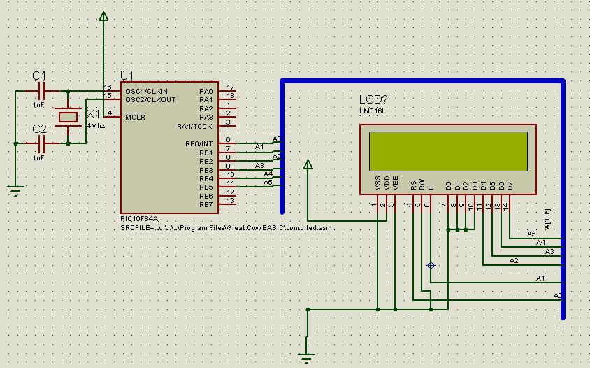
This type of LCD can use in two mode; 4 bit mode and 8 bit mode. The different between two is 4 bit mode requires less wire connection than 8 bit mode. In this tutorial I use 4-bit mode and the circuit as below.


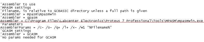
I discover that using this compiler more easily than using PicBasic Pro. It only requires 8 lines of definition and the LCD ready to work. The definition code as below:

'Chip model
#chip 16F84A, 4                                 ‘I use 16F84A chip
#define LCD_IO 4                               ‘tell the compiler to use 4-bit mode
#define LCD_RS PORTB.0                 ‘set Register Select to Port B pin 0
#define LCD_NO_RW                        ‘tell the compiler Read/Write pin is ground
#define LCD_Enable PORTB.1          ‘set Enable pin to Port B pin 1
#define LCD_DB4 PORTB.2               ‘set D4 to Port B pin 2 and so on…
#define LCD_DB5 PORTB.3
#define LCD_DB6 PORTB.4
#define LCD_DB7 PORTB.5

After that you can start to display any text or number at your LCD. Use Print command to display the text or number as below but you must put Locate command as well to tell the compiler where to put the text. The syntax of Locate is Locate line, column.

Locate 0, 0
Print "Hello World"
wait 10 ms

And the last part is to make an animation of star. The code is below.

For StarPos = 0 To 16
If StarPos = 0 Then
Put 0, 16, 32
Put 0, 0, 42
Else
Put 0, StarPos - 1, 32
Put 0, StarPos, 42
End If
Wait 250 ms
Next

Now you can compiler the code and test it. You can have more info here


Full code as below :

'Chip model
#chip 16F84A, 4

#define LCD_IO 4
#define LCD_RS PORTB.0
#define LCD_NO_RW
#define LCD_Enable PORTB.1
#define LCD_DB4 PORTB.2
#define LCD_DB5 PORTB.3
#define LCD_DB6 PORTB.4
#define LCD_DB7 PORTB.5


Locate 0, 0
Print "Hello World"
wait 10 ms


For StarPos = 0 To 16
If StarPos = 0 Then
Put 0, 16, 32
Put 0, 0, 42
Else
Put 0, StarPos - 1, 32
Put 0, StarPos, 42
End If
Wait 250 ms
Next

Sunday, October 17, 2010

GCBASIC Tutorial 2 part 2: 3 wires 7 segment LED display using open source PIC compiler


As in part 1 I have show how to program a single 7 segments with 3 wires. In this tutorial I have modify the last circuit by add-on another two 7 segments and two IC 4094 Shift register.

The three 7 segment and three IC 4094 Shift register have been connected as picture above. Take note on the CLK and STB pin of the three IC 4094. There are connecting each others with RB1 and RB2 of PIC respectively. The purpose of connection is to sharing Clock and Strobe signal output from PIC.

However the data output from PIC is only connected to pin2 of U2. At the same time pin 2 of U3 and U4 are cascading by connecting QS of the previous 4094. This can be explained that the 8 bit data of U2 is cascading to U3 and so on.

'A program to flash two LEDs on PORTB, bits 0 and 1

'Chip model
#chip 16F84a, 4

#define data PORTB.0 'set as data
#define clock PORTB.1 'set as clock
#define strobe PORTB.2 'set as strobe

dim x as byte

'Set the pin directions
dir PORTB out


'Main routine
Start:

set data off 'put data low
for loopcounter = 1 to 8
PulseOut clock, 10 ms
PulseOut strobe, 10 ms
next


for x = 1 to 10 ‘#1
readtable tsegment2,x,segment
gosub display
next

table tsegment
b'01111110 '#0
b'00110000 '#1
b'01101101 '#2
b'01111001 '#3
b'00110011 '#4
b'01011011 '#5
b'01011111 '#6
b'01110000 '#7
b'01111111 '#8
b'01111011 '#9
end table

end

display: #2
for loopcounter = 1 to 7
nsegment = segment % 2
data = nsegment
PulseOut clock, 10 ms
segment = segment / 2
next

data = segment
PulseOut clock, 10 ms
PulseOut strobe, 100 ms
return

The program above is identical with previous program but only two parts was add-on. At #1 I use for..next cycle to have 7 segment to shows number from 0 to 9. It could produce only single number at one time. The readtable function is used to call a number arrangement which is stored in tsegment table. The number arrangements are in binary and it’s responding to the arrangement of the 7 segment.

At #2 I used label to display number on 7 segments. The name of the label is Display. The line inside of display label is identical line from previous program at #4. The GOSUB function had used inside for..next loop at #1 in order to jump into display label and return back after finish their job.

When you run the program it will produce the number at first 7 segments only. A few second after that the number will shift to second 7 segments. However first 7 segment will produce a new number. Once again a few second after that the number at second 7 segments will shift to third 7 segments. The second 7 segment will replace with the number previously at first 7 segments.

The shift number can be explained due to 4094 are connected in cascading. Actually the PIC sends 8 bit data to the U2 only. The U2 then shift the previous data into U3 after received new data from PIC. The U3 will store the data and display on 7 segments when STB is high. It then repeated the process for the rest of 4094.

Saturday, October 9, 2010

GCBASIC Tutorial 2 part 1: 3 wires 7 segment LED display using open source PIC compiler


Last tutorial I has give a simple example how to use open source PIC basic using GCBasic. This tutorial I used 7 segments to display a number using PIC16F84A. Usually 7 segments need about 8 wires to operate using PIC but in this tutorial I only used 3 wires.

Seven segments display have 7 elements of LED to show Arabic numerals. Each element of LED can be ON or OFF and they can be combining in order to produce representation of the number. They also can be produce letters but it limits letters A to G only. The elements of LED is arrange as below.
Typically 7 segments have two types. The types are common cathode and common anode. The common cathode is referring to negative terminals and anode is positive terminal. It means the negative or positive terminals of the each LED elements are connected together and brought to common pin. Hence a 7 segments plus decimal point package will only require nine pins.

As mention earlier I used only 3 wires to operate the 7 segments. In order to have that IC 4094 shift register was used.

The 4094 is an 8 bit SIPO shift latch register. The device consist of 8 bit shift register and an 8 bit latch with 3 state output. It also have 3 importance input. The inputs are strobe, serial in and clock. The circuit connection between the PIC16F84A, IC 4094 and 7 segments were connected as below.


The Data, clock and strobe are connected to RB0, RB1 and RB2 respectively. The 7 segments are connected to Q0 to Q7 pins of 4094 with A to G pins and DP pin of 7 segments. The type of 7 segments is common cathode. The OE is connected to 5V. It makes sure the IC is always ready to operate.

The data will send by PIC16F84A to 4094 trough pin of RB0. The 8 bit data of the PIC will shift serially to the 4094. The IC then shift the data to shift registers at the positive transition of the clock input. The clock input also trigger by the PIC. When the strobe input is give high by the PIC the data will propagates to the output pins of Q0 to Q7.

The output of the 4094 then will ON or OFF the 7 segments LED depending on the data input. The 7 segments will display a number responding of it. Below is the program of the microcontroller.

'A program to flash two LEDs on PORTB, bits 0 and 1

'Chip model
#chip 16F84a, 4

#define data PORTB.0 'set as data #1
#define clock PORTB.1 'set as clock
#define strobe PORTB.2 'set as strobe

'Set the pin directions #2
dir PORTB out


'Main routine
Start:

set data off 'put data low #3
for loopcounter = 1 to 8
PulseOut clock, 10 ms
PulseOut strobe, 10 ms
next

segment = b'11111100 ' #4

for loopcounter = 1 to 7
nsegment = segment % 2
data = nsegment
PulseOut clock, 10 ms
PulseOut strobe, 100 ms
segment = segment / 2
next

data = segment
PulseOut clock, 10 ms
PulseOut strobe, 10 ms
End

At #1 and #2 is to define the pin of the PIC16F84A and the flow of the direction. At #3 the data is set low to clean 7 segments from showing unwanted number.

At #4 the variable of segment is stored the data input. In this case it stored the data to display number 1.

After that variable of nsegment is used to get least significant bit (LSB) of the segment and send to 4094 trough data pin. It then followed by the positive transition of the clock about 10 milliseconds to have the 4094 shifted the data into shift register. The segment variable then will reduce the bit to 7 by dropping the LSB. It will repeat 7 times.

The last bit of the segment is not dividing by 2 because it only have one bit. The bit number will send to data pin to complete the process of sending data to 4094. At last the high output of strobe will send to 4094 in order to display a number on 7 segments.

Video for tutorial as below (please take note this video is no audio).

Thursday, September 30, 2010

GCBASIC Tutorial #1: Play with LED

The first tutorial I will focus on how to light up LED. If you’re reading any programming books you will found their first tutorial is about how to print ‘Hello World’. Same as any programming language you needed to know the basic programming of microcontroller.

As I mention in last post I only focus on PIC16F84a microcontroller. Below is the basic circuit of PIC16F84a with 8 LED. It used clock of 4 MHz.


The basic program of microcontroller is to light up the LED. It will light up for the first LED and then to second LED until last LED. At one time only one LED is ON for 250 milliseconds. If all LED is ON it will repeat to the first LED.

To program a microcontroller, firstly you need to declare a type of microcontroller. As for this tutorial I use PIC16F84a. The #chip is used to determine the program to refer microcontroller and clock is used.

Syntax: #chip model, speed

'A program to flash LED in sequence

'Chip model
#chip 16F84a, 4   ‘used PIC16F84a with clock of 4 Mhz

After that you need to set the direction of the port. The direction is the input/output of the port. Each port usually consists of 4 to 8 pins. Each pin you can set either as the input or output. The #dir is used to set direction of the port.

Syntax:
    Dir port.bit {In | Out} (Individual Form)
    Dir port {In | Out | DirectionByte} (Entire Port Form)

'Set the pin directions
dir PORTB out                        ‘All pin in Port B is set output direction

Once define is complete you can start program the microcontroller. Below you can find that I use two styles to light up the LED.

First I used simple PORTB. It can set which pin to ON. As an example I set only pin 0 is ON. It is set used decimal number. You also can set in binary or hexadecimal as below.

PORTB = b’00000001’ or PORTB = h’01’

Second method I used #rotate command. It will rotate variable in specified direction. In this case I use to rotate PORTB variable to the left. Example below will describe better.

Syntax:    
    Rotate variable {Left | Right} [Simple]

00000001 -> 00000010 -> 00000100 -> 00001000 -> 00010000 -> 00100000 -> 01000000 -> 10000000

However to have the variable to move from right to left you need a loop. #for…next command was used. Below is the main program for this tutorial. Not to forget #wait command is used to delay for specified time.

'Main routine
Start:

 'Turn one LED on, the other off
 PORTB = 1
 wait 250 ms

 for loop = 1 to 7       
            rotate PORTB left simple
            wait 250 ms    
 next

goto Start

You can copy all text programming from declaration to main program as above in one file. I suggested you copy all that in notepad and save the file as LED.txt.

After that you can compile it using GCBASIC. The hex file will produce by the compiler. Take the hex file to download into your microcontroller. Good luck.

Click the images below to enlarge and watch the LED run in animation.

Monday, September 27, 2010

3 Step to setup microcontroller project

Electronic projects will not complete without microcontroller. It is the most easier and low cost project you could ever build. You only need to program and it will run accordingly. However if you want to start microcontroller projects you need only three step to setup a project as describe below.

1. Need microcontroller
Microcontroller is small device consists of CPU, memory (RAM and ROM), I/O port, serial and parallel port, timers, and some type of microcontroller have built in Analog to Digital (A/D) and Digital to Analog (D/A). The cost of single microcontroller relatively is cheap compare to microprocessor.

For the mean time I only focus microcontroller of PIC. After this I will write the tutorial only for PIC16F84A and PIC16F877A. This PIC is the easiest to setup and to program for the beginner.

If you search through internet you will get more type of microcontroller. After all is up to you to decide the best. I suggest for the beginner you can start with PIC to gain an experience.

2. Compiler
Before I go too far it is better I introduce the compiler. The compiler will able a user to program in high-level language. It is using English style language and easier than assembly language.

As student or beginner user, I prefer to use open source compiler. There are varieties of open source compiler available in internet. The popular open source compiler is Small Device C compiler (SDCC) or Great Cow Basic (GCBASIC). SDCC is using C language and GCBASIC using Basic language.

The compiler also will execute your program and produce hex file. The hex file is binary code. It will upload to your microcontroller using programmer. It also produce assembly file. The file could use to simulate your code using simulation program.

3. Programmer
Programmer consists of software and hardware to upload hex file into microcontroller. The software is a program to communicate with programmer hardware via serial or parallel communication. It will take hex file produce by compiler to upload into microcontroller.

The programmer hardware however is to burn binary code from hex file into ROM of microcontroller. After it successfully burned the microcontroller is ready to use.

Software and hardware programmer have varieties type in market. You can buy or build it yourself. There are many circuits available in internet to setup hardware yourself and download software freely. The most popular software and hardware of programmer is at http://www.winpicprog.co.uk/

Finally I hope that you now have an idea how to setup microcontroller project. I also will try to put some tutorial to program microcontroller. The compiler that I used is GCBASIC compiler.

Saturday, September 25, 2010

Great Cow Basic (GCBASIC) installation guide

After struggling to install GCBasic for few days finally I make it. I had installed two version of GCBasic. The versions are Version 24/2/2007 and 6/2/2010. You can download it at http://gcbasic.sourceforge.net/download.html.

These two versions give different resulted. I prefer to use version 6/2/2010 because it give satisfying resulted. However I make an adjustment to gcbasic.ini. For the version 24/2/2007 I think the gputils was outdated. If you want to use it make sure you download GCBASIC minimal 0903.exe and download the latest gputils.

In this post I only focus to version 6/2/2010. The adjustment gcbasic.ini is the assembler path. I used MPWINASM to compile the program. Luckily I already have MPASM which is I did installed the Proteus software before. It will produce asm file, hex file and lst file when you compile your program. However you can use either MPASM or GPASM to compile your program.


The gcbasic.ini adjustment
Prior to use GCBasic you must make sure that gcbacic.ini correctly modifies. At your GCBasic folder you can edit sample gcbasic.ini file in notepad. Prior to that makes sure rename the file to gcbasic.ini. Then open it using notepad to modify.


Observe the red underline as picture above (Please click picture to enlarge). I rewrite the assembler path to my Proteus path so that I can access my MPASM in Proteus without to install twice.

First program
After the gcbasic.ini correctly setup, it is time to test the software. The test can be performing by programming GCBASIC first. In this example I write a program to ON a led in pin 0 of port B. I use PIC16F84A with clock of 4 MHz.

'A program to ON a  LEDs on PORTB,

'Chip model
#chip 16F84a, 4

'Set the pin directions
dir PORTB.0 out

'Main routine
Start:

 'Turn one LED on, the other off
 SET PORTB.0 ON

goto Start

 Copy the program above into your notepad and save it to test.txt. I suggest that the file is place on your desktop (only for this tutorial). Open your GCBasic folder, usually c:\program files\Great Cow BASIC.

In this folder you will see gcbasic.exe file. Drag your test.txt file at your desktop onto gcbasic.exe. After that your test.txt will compile and it will automatically created new files. It will produce compiled.asm, compiled.hex and compiled.lst.

Use compiled.hex to programmer into your PIC16F84a. I consider that you already know how to programmer the PIC. If don’t know… please google…

However for this program I not try in real PIC. I just use Proteus to simulate the program. Below is the circuit diagram for this program. Good luck.


Wednesday, August 18, 2010

8 bit microcontroller

Hi all,

This is my first posting in this blog. I created this blog because want to share with readers about all relating with microcontoller. It will cover tutorials, circuit designs, project ideas, share articles and codes.

I am planning to share at least 10 simple projects using PIC microcontroller until end of 2010. I will post as tutorial format using either assembly language or high level languages such as GCBASIC or SDCC.

Hope that I could share my experience as much as I could. Lastly thank you to visit my site and enjoy reading.